Unlock peak precision: why GNSS and correction availability matters
The advantages of multi-constellation, multi-frequency GNSS receivers and corrections are widely promoted. Major manufacturers advocate for customers to invest in more frequencies, greater constellation access, increased signal tracking channels and top-tier correction products that support all signals and constellations.
While these advanced technologies require a financial commitment, the long-term gains can be considerable. Here are three important factors to evaluate concerning availability and its diverse value.
Availability of constellations
GNSS constellations refer to global and regional constellations that provide GNSS signals. Global constellations include: GPS (USA) with 31 operational satellites, GLONASS (Russia) with 24 operational satellites, Galileo (EU) with 24 operational satellites (with 2 backups), and BeiDou (China) with 35 operational satellites. Regional constellations include: NavIC (India) with 7 operational satellites, and QZSS (Japan) with 5 operational satellites.
These satellite counts are current at the time of this writing, and of course can fluctuate due to decommissioning, maintenance, or testing. Quantum computing allows us to calculate that there are 126 of these satellites available, with some portion of those being obscured to the observer by the Earth at any given time.
On your receiver
The impact of tracking multiple constellations on your receiver is a simple reality of geometry. This geometry we’re referring to in the geodetic world is referred to as dilution of precision (DOP). Much has been written regarding DOP, the impact of poor geometry on our ability to accurately estimate the range to a satellite (or a number of satellites). Generally speaking, moving from a DOP of 1 to a DOP of 2 doubles the uncertainty in your ranging errors.
In the early GPS-only days, DOP was a crucial consideration when planning GPS missions. With the addition of GLONASS, our likelihood of bad DOP decreased, and with the addition of Galileo, our likelihood of bad DOP decreased even further, and finally with the addition of BeiDou, most of us stopped thinking about DOP altogether. Note that when large portions of the sky above are obscured (and therefore line of sight to GNSS satellites is impossible), such as when you are in an “urban canyon,” or even an actual canyon, your DOP may be increased–and in these locations, DOP should still matter to you.
A good exercise that allows you to visualize the geometry of the constellation is to navigate to gnssplanning.com, put in your location, and take a look at the resulting sky plots.
Here’s an example:
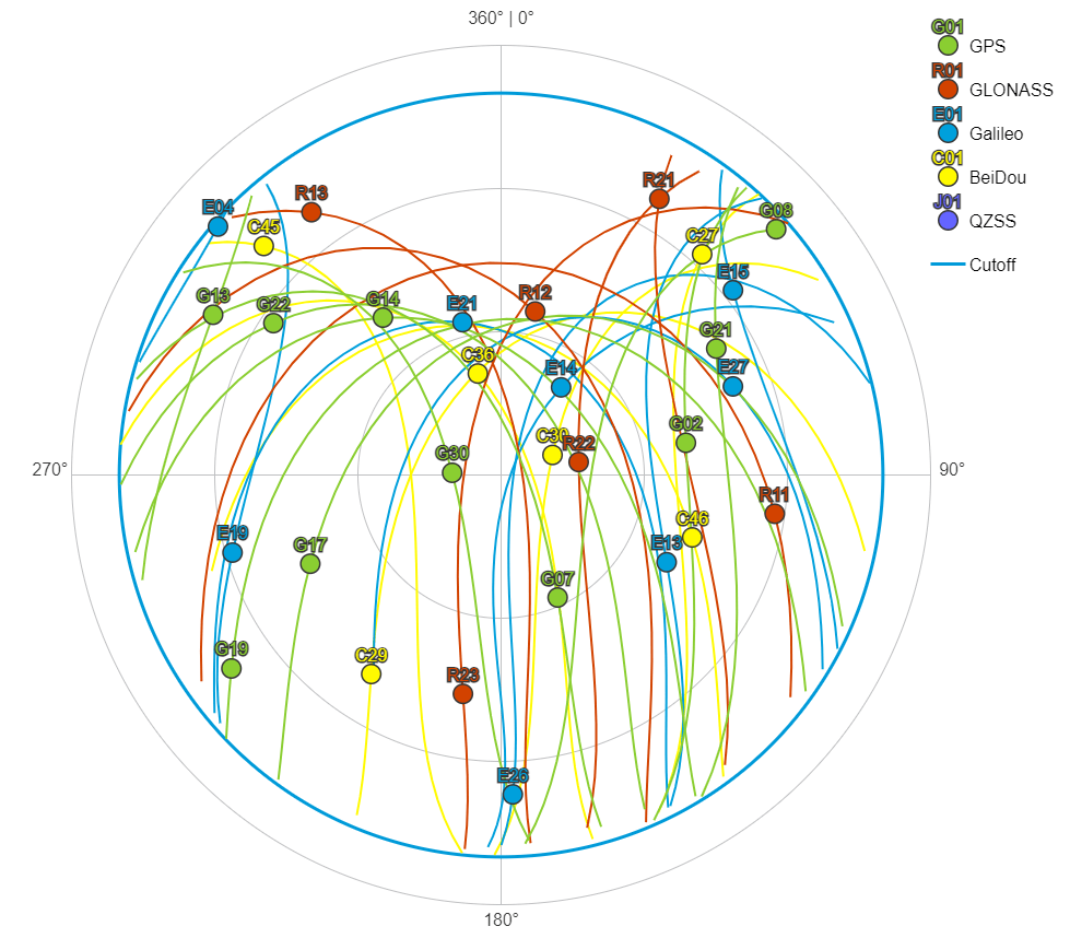
There are 30 satellites above this location at the given time. The geometry of these satellites is quite good: satellites appear in each quadrant, and at varying elevations from near the horizon cutoff angle to the near zenith in each quadrant.
We can also look at predicted DOP in a linear chart:

Remember: the lower the DOP value, the better the precision of your measurement estimation. A DOP of less than one is ideal, and DOP values of five or greater are considered to be too poor for precision measurement. At this location and time, our full-constellation receiver can be expected to deliver excellent results, assuming that there are no obstructions to block the line of sight to these satellites on our site.
If we uncheck the constellation boxes on gnssplanning.com, we can see the obvious impact of missing particular constellations:
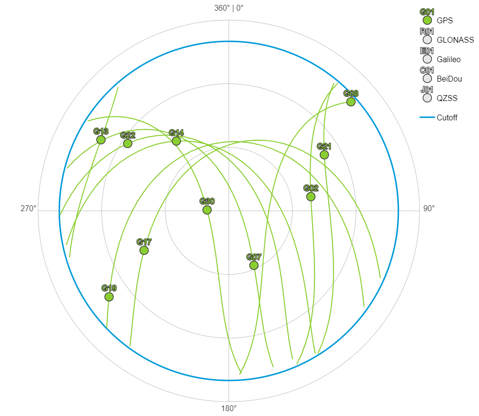
If we’re tracking GPS-only at the same location and time, we’re only left with 10 satellites. The geometry of those ten satellites is now quite a bit different: while we still have satellites in each quadrant, we certainly do not have satellites in each quadrant at as many elevations.
Note in particular that we have a single satellite in the lower right quadrant, that is perhaps approaching the zenith, but no satellites available near the horizon in that quadrant. Here again we can switch to a linear chart to evaluate our estimate DOP:

It’s important to note the change of the vertical scale of this chart (from 0 to 10 instead of 0 to 2.5 as in the previous chart). We can see that shortly after 02:00 the DOP values are estimated to be quite poor–so consideration should be given to avoiding this period of time if precise measurements are required. We see a small spike shortly after 12:00 as well — probably a good excuse to take a lunch break.
If you’ve been surveying with GNSS equipment (or maybe “GPS equipment”) long enough, you probably remember planning being a reality of the job, or at the very least you probably experienced poor performance at particular times of the day when satellite geometry was poor, and DOP values were high. If you buy the high-end receiver, but forgo the added constellations, sticking with GPS and GLONASS-only, this might be your reality today.
In your correction
Modern GNSS solutions tend to use one of a few methods to achieve accuracy: differential RTK, PPP or post-processing. Let’s focus on the real-time applications that are more common:
Differential real-time kinematic refers to workflows where you use multiple receivers, one operating as a base station, and one operating as a rover, communicating across a radio or Internet link. It also includes real-time networks, like Trimble® VRS Now™, where a number of reference stations are used to provide a differential correction to the rover, communicating across an Internet link.
The principle is that your base station (or reference stations) has a known location, and therefore when range is estimated to each satellite visible above that station, the error becomes knowable. For instance, if the range estimation to a particular satellite is 20,200,000.10 m, and the calculated distance to that satellite from the known location is 20,200,000.08 m, the knowable error is the difference–0.02 m. This is a bit simplified, but suffice it to say that similar information can then be sent to the rover receiver, and its range estimations to that same satellite can be differenced by the value.
The obvious problem is that if the base receiver, or reference station receivers, are not tracking the same satellites as the rover receiver, you would be lacking the necessary information to difference the measurement estimation for that satellite range at the rover.
The result is that a satellite tracked at the rover, but not at the base, would not be used in the position solution. As soon as you start removing satellites from the solution, you have to start worrying about the geometry of the solution as demonstrated in the previous DOP information above.
Precise point positioning refers to workflows where your rover receiver uses an outside source of modeled estimations of the impact of the satellite orbits, clocks, and atmosphere at the rover position. These correction models are typically delivered via a geostationary satellite broadcasting in the L-band, or via the Internet. Trimble RTX® correction service is a PPP service that provides this information, and is available for Trimble GNSS receivers.
Trimble RTX provides corrections for GPS, GLONASS, Galileo, BeiDou and QZSS constellations. Not all PPP services cover all constellations. Here again, if the reference stations for the PPP service lack constellation support, while your receiver has full constellation support, you will not be able to use the missing satellites in your position solution. The same dilution of precision should be expected in this circumstance, and your time to converge to a precise position would drastically increase.
Another PPP solution is Galileo HAS, which is part of the European Space Agency’s Open Services. Galileo HAS specifies two solution types: GAL-only and GAL+GPS. The GAL+GPS solution is specified at around 15 cm horizontal, and around 20 cm vertical (both RMS). The GAL-only solution is specified at around 25 cm horizontal, 30 centimeters vertical (both RMS). Certainly the lack of constellation availability plays a role in these different specification levels.
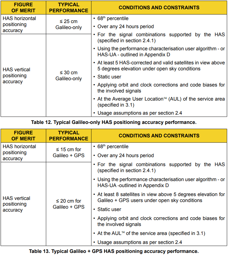
Again, consider the impact to your convergence with fewer constellations available. It’s also possible that your GNSS receiver does not track the Galileo E6 signal, as it is relatively new. Without GAL E6 tracking, you cannot use the GAL HAS service. We’ll take a look at how signal availability impacts performance in the section below.
Availability of signal
Each GNSS constellation has a different mix of signals that are available, however, not all signals that are available are specifically used for navigation (for instance, the GPS L4 signal is used for nuclear detonation detection and scientific study). The table below has the navigation signals available by constellation; NavIC has been excluded as it is incomplete at the time of this writing.
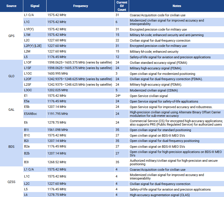
*Some say “26”, but two of the GAL SVs are for backup.
Much like the discussion above regarding constellation tracking, the tracking of signals is important for the quality of your position estimation. Not only are we using the information encoded on the signal for ranging estimation (“code pseudorange”), but we also use the signal carrier wave itself ("carrier phase ranging").
It’s important to note that each satellite generates a unique code and then broadcasts it on the carrier at the same frequency as all of the other satellites. To say that in a different way, “satellite 14” generates a different code than “satellite 16,” and simultaneously both are broadcasting their unique code on the same carrier frequency (e.g. L1, L5, etc.).
The phase shift on the GNSS carrier wave, which is often referred to as the “GPS observable,” is achieved by instantaneously switching the phase by 180°. Codes are modulated onto the carrier wave by multiplication with the code states. Each shift from 1 to -1, or -1 to 1 is represented by the 180° phase shift in the carrier. These are referred to as “code chips.”
Because the atomic clock (oscillator) in the satellite and the clock (temperature controlled quartz crystal oscillator) in the GNSS receiver are never perfectly synchronized, the receiver will continuously adjust its replica to try to match what’s being sent from the satellite on each signal (i.e. for L1, or for L5, etc.). By correlating the GNSS observable and the replica, the receiver is able to calculate the range to the satellite.
On your receiver
In the fine print for your GNSS receiver specifications, you will find the receiver’s ability to track signals. For quite some time, the “channel wars” raged on amongst manufacturers to have the largest channel count. From a practical standpoint, each channel allows you to track a single signal from a single satellite. You can add up all the GNSS satellites that broadcast the signals in the table above, and come up with a maximum theoretical amount of channels to track everything that is currently available (I’ll save you the math: the total on the table is 593!).
Tracking this many signals is implausible, of course, because at any given time, the Earth under your feet is in the way of a number of satellites, and so the signals from those satellites can’t possibly reach you. There’s some notion that having more channels available might make your receiver “future proof,” but there’s no guarantee that you’ll be able to support a new signal given the physical characteristics of the antenna in the receiver, or even that the application firmware in the receiver is able to process that new signal.
As an example, the GPS/GLO/GAL/BDS constellations all broadcast within the L-band (1-2 GHz), while the new NavIC constellation has some signals in the S-Band (2-3 GHz). You can ask your manufacturer if the “future proof” integrated receiver (with its built-in antenna) you bought a couple years ago, with an antenna tuned for L-band signals, will pick up the signals from the S-band.
A better way to future proof yourself is to budget for replacement of your GNSS receiver every 3-7 years (depending on when you bought in on the manufacturer’s development cycle). Over this course of time there are likely improvements to cellular chipsets, memory, and processors that will be a big step forward, along with the addition of taking advantage of whatever new signals may come along.
While this all makes for a compelling marketing message, the ability to track signals is of course important for precise range estimates to the GNSS satellites. A significant portion of the ionospheric bias can be removed using dual-frequency statistical analysis, as the dispersive nature of the ionosphere affects higher frequencies less, and lower frequencies more.
When comparing L1 to L2, and L1 to L5, and L2 to L5, for example, the receiver can model much of the ionospheric bias. Advanced algorithms like Trimble IonoGuard™ have proven their value in this regard.
Also a reality is that the new signals tend to have more safeguards built into them to prevent spoofing. With our ever increasing dependence on GNSS positioning, bad actors have found ways to cause mischief with jamming and spoofing. The more modern signals are harder to spoof, at least as compared to the “legacy” signals like L1 C/A. If your receiver is “signal agnostic” and can estimate a position based on any signal available from any constellation, detection and rejection of spoofed signals is mitigated by the availability of additional signals on which to base those estimates.
In your correction
As in the constellation discussion above, your correction source must support as many signals as possible for highly performant positioning. Looking at differential workflows, if your base station or your network is lacking signals that your rover has, you’re not making use of them. Likewise, if your PPP service lacks signal support, your receiver will not benefit from the increased signal count and likely your convergence times will increase–in some cases dramatically.
Let’s take a closer look at PPP convergence. Here we take two receivers and log their positioning performance. Each receiver is reset every 10 minutes, and the time it takes to converge to a precise position utilizing PPP can be visually evaluated. Both receivers are in an open sky environment with very little interference and multipath. Trimble RTX is used as the correction source, and corrects the following signals:
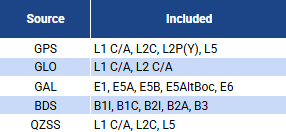
Receiver A: Missing constellations GAL & BDS and all of their signals

Receiver B: No missing signals

These charts demonstrate 3D RMS of two selected resets, and the convergence to a precise position following that reset. These receivers are identical other than the signals that were enabled on them, and share the same geodetic grade antenna through the use of a cable splitter. Note the smoothness of the convergence curve where all signals are present.
And also, how quickly ambiguities are mitigated: the plot with full signal support descends to an accurate position much more rapidly, and shows that the receiver was able to estimate a 3D position down to less than 3cm RMS, while the limited receiver only achieved less than 4cm RMS within the time allowed.
A 2D scatter plot of the observations also shows this difference quite clearly. Here we look at the horizontal:
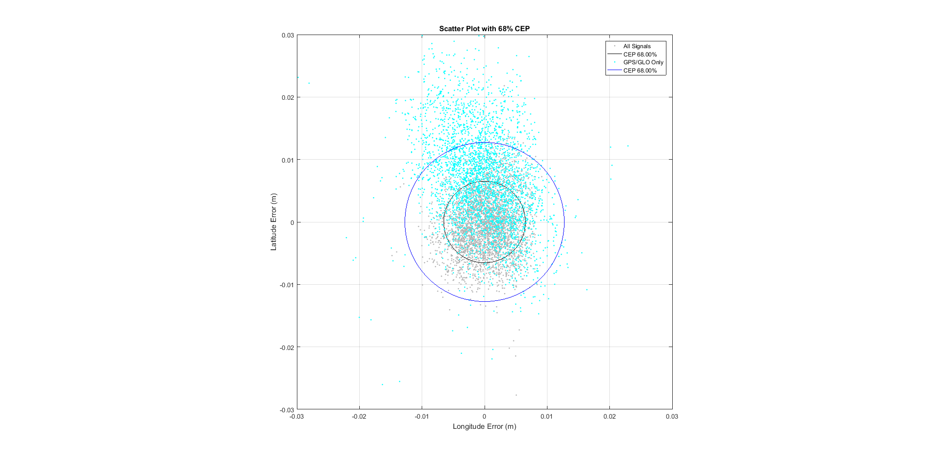
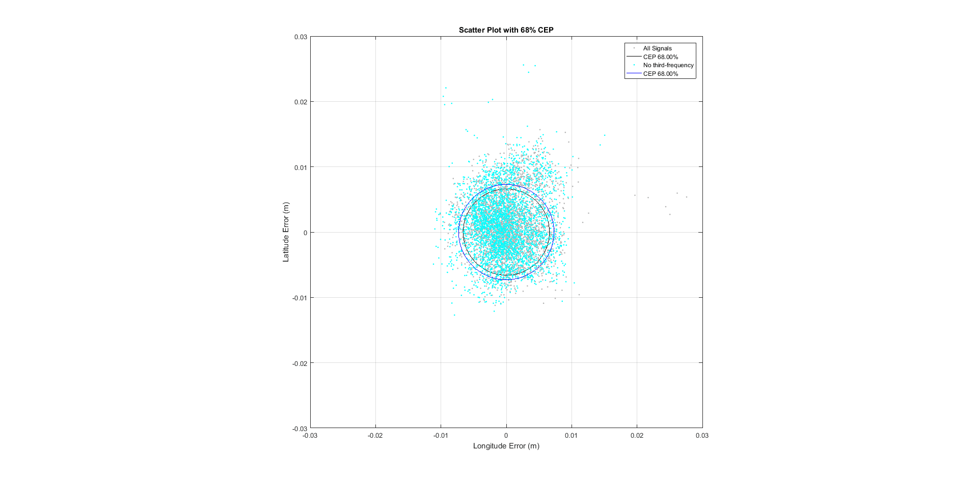
We can repeat the experiment in a “dual frequency” configuration, where all constellations are present, but only L1 and L2 frequencies are utilized. Our expectation should be that there is an improvement over GPS/GLO-only tracking, but still an advantage to “third frequency” tracking.
Receiver A: Missing signals GPS L5, GLO L3, GAL E6, BDS B3, QZSS L5

Receiver B: No missing signals

Here again we can compare the 3D RMS of two selected resets, and the convergence to a precise position following that reset. Our expectations are met in that there is an improvement over GPS/GLO-only tracking, but still an advantage to “third frequency” tracking: while both solutions made it to the <3cm 3D RMS threshold, it’s clear that there is more stability with the third frequency.
The scatter plot demonstrates the slight improvement of triple-frequency support over dual-frequency as well:
Availability of correction
Our final consideration for availability is whether or not our correction data is available in a timely manner, and contains the information needed to resolve GNSS satellite signal biases, and GNSS rover receiver biases. But what’s in a correction? How do different correction types help me to achieve precise measurements with my GNSS receiver?
Probably the first consideration is of the various correction methods, their delivery mechanisms, and any limitations you might have on your job site:
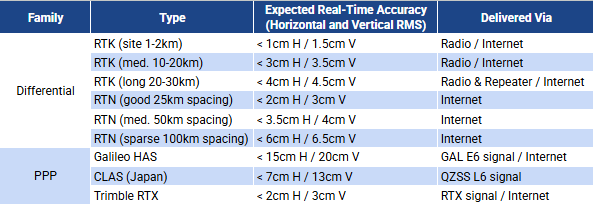
Does your job site have spotty Internet coverage? Is your job site near an international border where the usage of UHF or VHF radios might get you into serious legal trouble? Will the built-in radios of an integrated receiver get you the range you need for your entire area of interest? Is this job site within the coverage of a real-time network or a PPP service? Can you afford to have the field crews spend time every single day setting up a site base station and performing checks? Take a look at this blog article to take a deeper look at choosing the right GNSS correction method.
Latency of the correction
Timeliness of GNSS correction data will influence positional accuracy, but different applications will only reap the benefits of timely corrections up to a point. For instance, when controlling a machine or a fast-moving drone with GNSS, timeliness of corrections is more important than during a slower-moving task, like topographic surveying or staking out points.
Typically in these higher-dynamic applications, and applications with matched epoch corrections (as opposed to predicted corrections), lower-latency communication is required. It is possible with multi-constellation, multi-signal tracking, and inefficient communication protocols, to overwhelm the available bandwidth of some communication methods. The Internet, and technologies like Internet Base Station Service (IBSS) can potentially provide higher bandwidth over radio technologies like UHF/VHF, as an example.
With modern PVT engines and integrated inertial sensors, it is generally safe to say that latency can degrade positional accuracy at less than 1mm per second.
Here’s an example:

This may be fairly difficult to interpret given the small scale of the rate of change. If we zoom in a bit, hopefully it will be easier to understand:

Here we can see a bit more clearly. This is a zero baseline RTK solution (the base and rover share the same antenna). The red lines represent 68th percentile, the orange lines the 95th, and the yellow-orange lines the 99th. The blue line is the position estimate for latitude; and at time index 12:30:40.6, the RTK correction source is cut off.
Ordinarily you would expect to see errors increase at around 1mm per second, but in this case, we’re using a modern receiver using Trimble xFill® technology. Trimble xFill receives correction data from the Trimble RTX correction stream to mitigate satellite orbit and clock biases. In this case, we’re seeing a couple millimeters of error over ten seconds (0.2mm per second).
Additionally, with the full backup of Trimble RTX orbit, clock and atmospheric models, which is available in xFill-RTX mode, after an initial increase in error during xFill mode, the position accuracy stabilizes when the mode switches to xFill-RTX. In this plot, the RTK correction was cut off at time index 19:47:04.9, at which point the receiver went into xFill mode until 19:47:29.7, when it switched to xFill-RTX mode (where the line for the position changed from green to blue):

In this instance, we see a small shift of about 1mm in latitude, followed by a minute without a measurable change. The more modern GNSS receiver, with support for L-band corrections, and Trimble ProPoint® GNSS technology certainly pay dividends.
Components of the correction
The correction message can have information to provide the data needed to resolve ranging biases, but can also have additional data that can improve the reliability of your positioning, such as navigation message authentication, or integrity indicators. The available information is dependent on the protocol as well as the capability to generate the state space representative modeling.
Communication protocol
As you can imagine, not all communication protocols produce the same, dependable results. These protocols evolve over time, typically with improvements that will benefit you. If you’re still hopping onto an old, familiar mountpoint, you may want to consider what impact that might have on the timeliness and content of your correction stream. If you’re using repeaters, you should really consider the impact of the protocol. Let’s start with the availability of constellation and signals by protocol version:
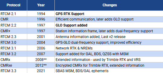
**CMRx protocol was introduced in 2008, but continues to evolve and is under active development by Trimble engineering R&D.
Consideration should be given to the amount of bandwidth available, and therefore the amount of data that is able to be sent to correct the rover position. Additionally, using mountpoints that are sending correction data using older versions of these protocols will be limited to sending the signals available for that protocol version and your positioning will be impacted as described above in the availability of signal section above.
Let’s take a closer look at some plots that show the number of available satellites, compared to the number of satellites used in the solution, and look at the impact on bandwidth of the protocol:
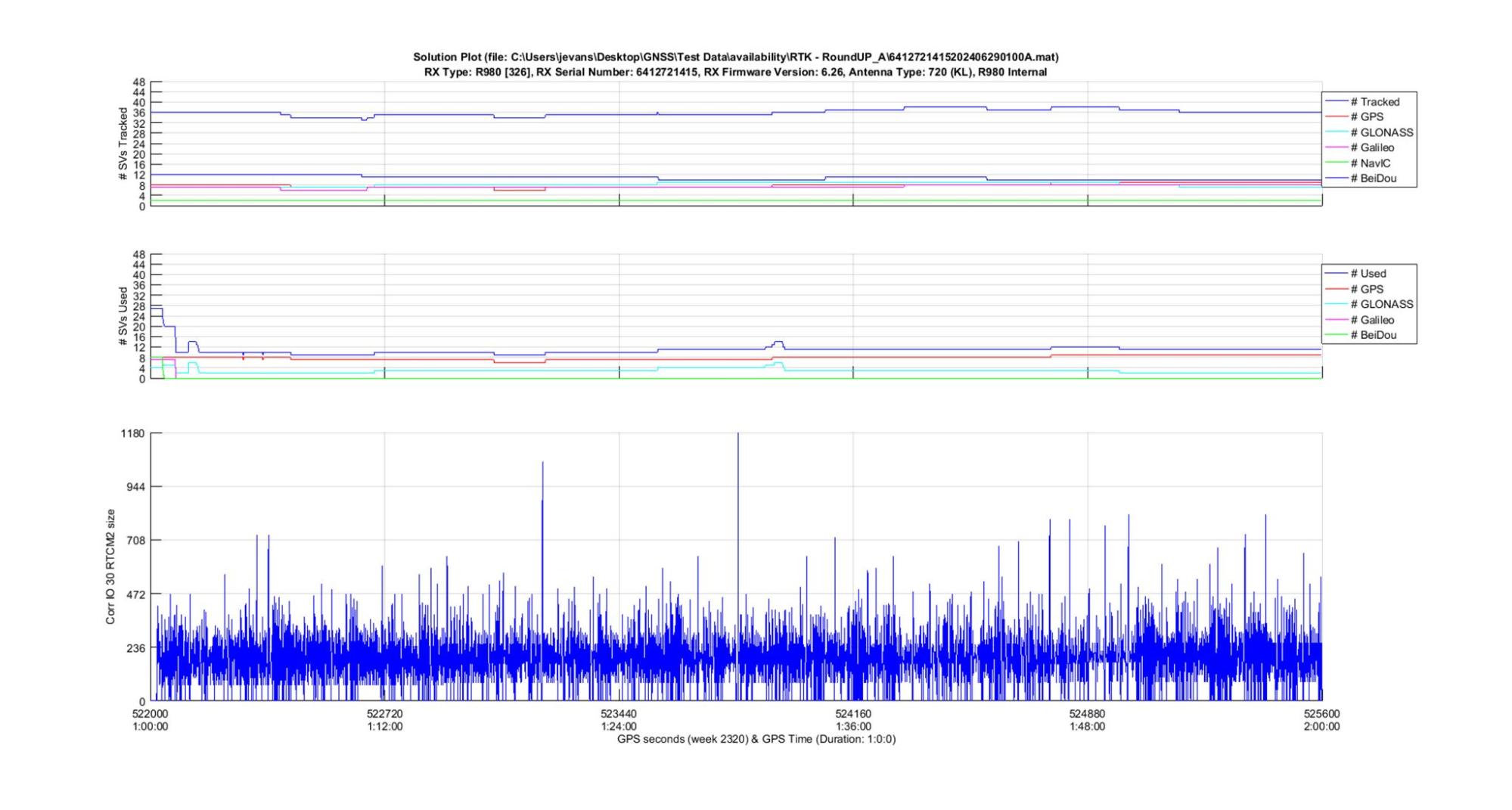
In summary, around 36 GNSS satellites were available, but only about 12 were being used because of the lack of GAL and BDS support in the protocol. The correction messages in RTCM2.x were relatively small–there isn’t a whole lot of information for just 12 satellites.
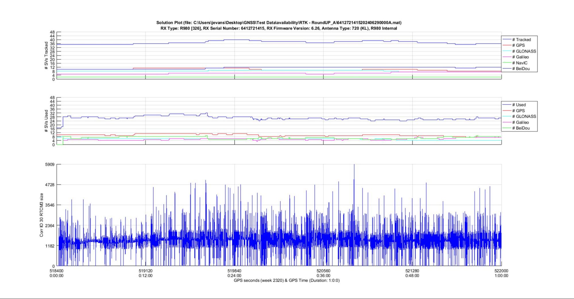
In summary, around 36 GNSS satellites were available, and around 28 were being used with the addition of GAL and BDS support in the protocol. The correction messages in RTCM3.x were roughly four times the size of RTCM2.x — expected when we have a much higher satellite used count.
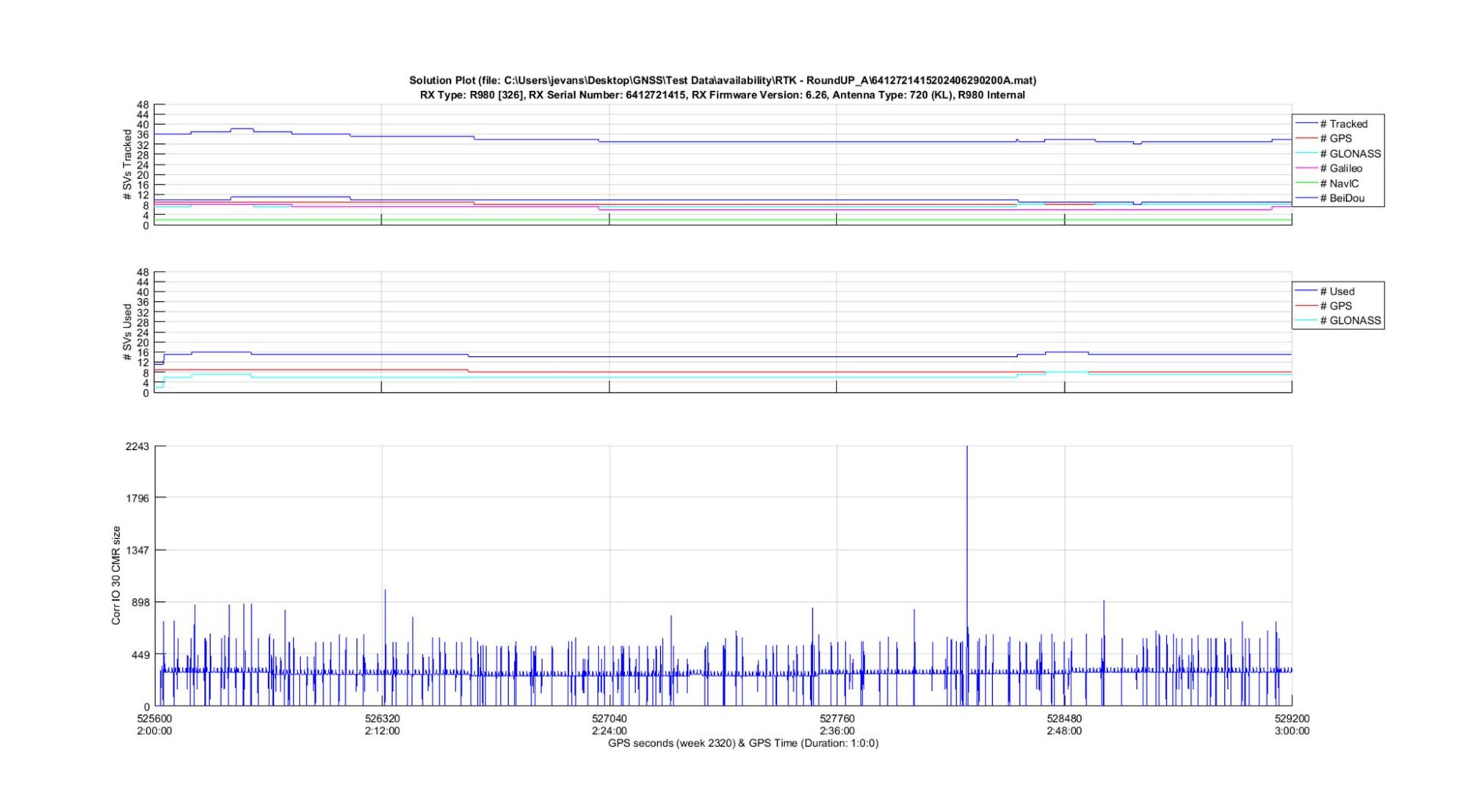
In summary, around 34 GNSS satellites were available, but only about 14 were being used because of the lack of GAL and BDS support. The correction messages in CMR are around the size of the RTCM2.x messages, but clearly a much more consistent data stream, making use of the available bandwidth.
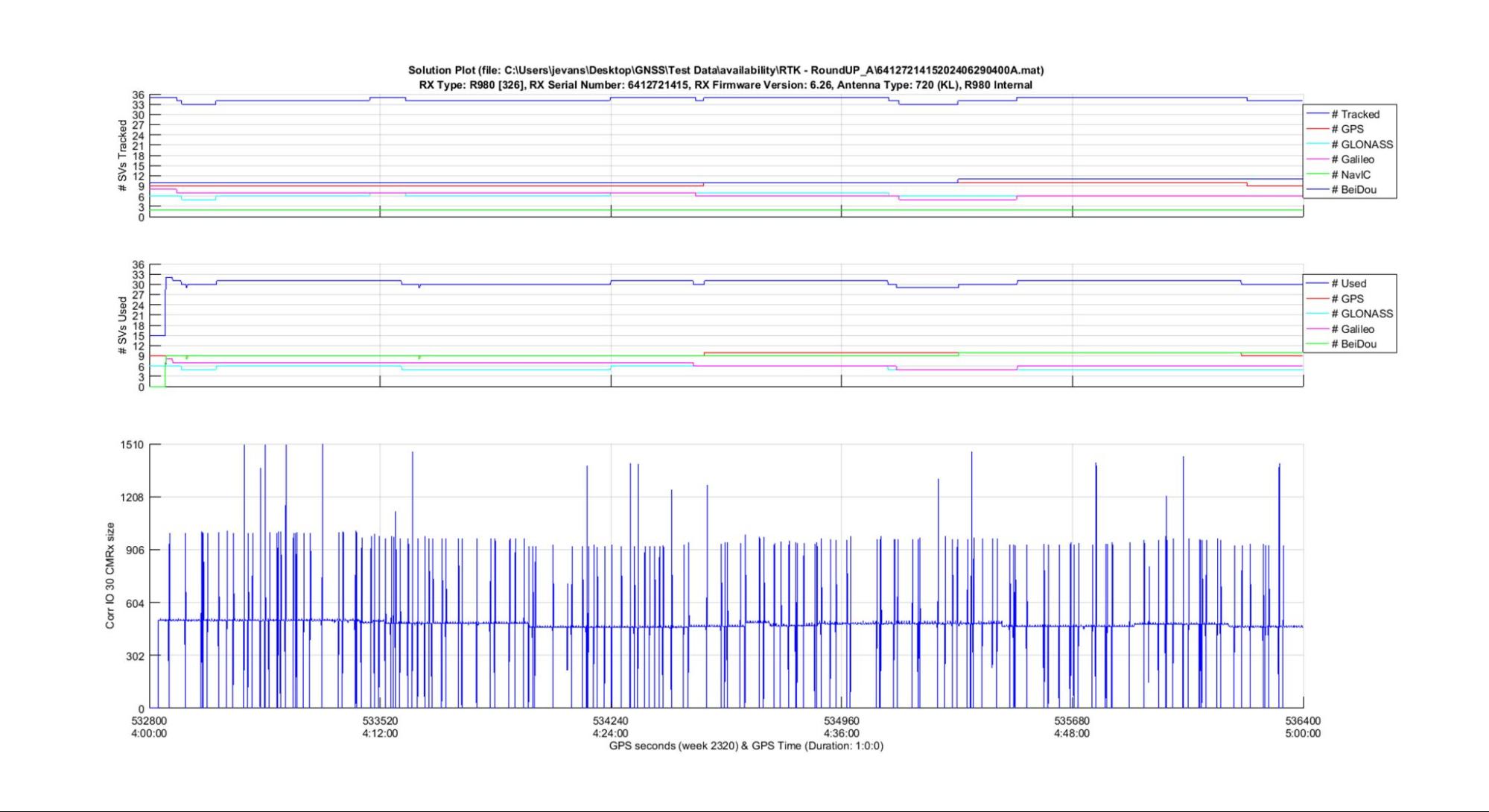
And finally, using CMRx, around 34 GNSS satellites were available, and around 30 were being used with the addition of GAL and BDS support in the protocol. The correction messages in CMRx are around the half the size of the RTCM3.x messages, with roughly the same satellite count, and clearly a much more consistent data stream.
Another consideration is the use of radio repeaters with these protocols. Mark Silver did some terrific analysis of this subject, and provides some practical suggestions. Suffice it to say that your repeat rate depends on you being able to complete the correction message before it is time to repeat it. This may limit you from broadcasting the message once a second or more, to a slower rate so that the entire message completes in time for the repeater to also send the message.
Or to say this in a different way, if your correction message takes 1.5 seconds, it doesn’t do you much good to repeat this message every 1 second, since you would be overlapping or missing half a second worth of data.
Correction contents
In table 5 above, we refer to “extended information” a number of times. This information does not necessarily correct your GNSS observations, but rather it can contribute to the overall dependability of your correction data, and therefore the dependability of your position calculation.
In some cases the extended information is required for other elements of the correction service. For instance, with Trimble RTX, subscription activations can be sent over the air, meaning that a device can connect to the correction stream, and be entitled to use that correction data. This subscription activation data does not contribute to your positioning, but it is important functionality for the service to make it easier to subscribe and use the service.
However, some of the extended information certainly contributes to the dependability of the position. Let’s take a look at some of the extended information parameters that are available when using the CMRx protocol for differential positioning with a Trimble VRS Now network, and the encrypted CMRx protocol that is used by Trimble RTX:
Trimble VRS CMRx extended information

Trimble RTX CMRx extended information

Correction availability
In order for the correction data to make it into the broadcast, not only does the protocol have to have support for these correction parameters, but the base station, or reference stations, have to be able to generate the necessary information. For instance, your base station cannot send information about a GNSS satellite it cannot track. This is a dynamic situation in scenarios where we consider jamming, spoofing or atmospheric interference that may suddenly be present at the base station (or reference station).
A good example of this can be illustrated from the RTX Server software, which employs hundreds of densely-spaced reference stations in a given area to generate regional atmospheric models for the ionosphere and troposphere. If enough reference stations are impacted, the contents of these corrections can certainly be changed.
One example would be a local spoofer who might be near one of the reference stations: since this reference station navigation message verification would not match another nearby station (that is not being impacted by the spoofer), this station could be flagged and down-weighted in the generation of corrections. Another example would be if an atmospheric event, such as a severe ionospheric gradient, impacted enough reference stations, the generation of regional models may become impacted, or even impossible.
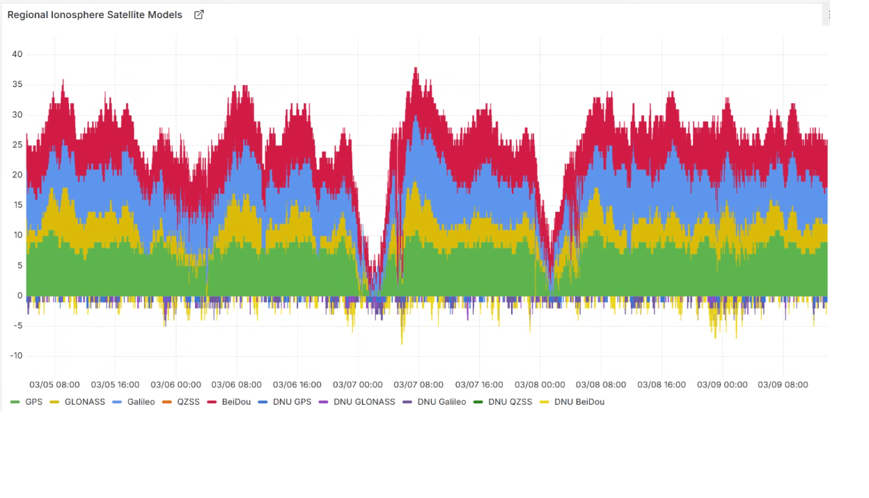
In the above plot, we can see that the dense regional reference stations were unable to be used to generate the regional model, as they were being impacted by high ionospheric gradient. During these times, the rover receiver would instead depend on the global ionospheric models, rather than the regional models–this would cause a longer convergence time to reach a precise position. A similar impact could be felt on a VRS Network as well.
Conclusion
We started this journey of availability by considering the extra cost of GNSS receivers and correction services. Often consumers can find lower-cost GNSS receivers, and lower cost, or even no cost, correction services. What these receivers or correction services lack in terms of constellation support, signal support, and availability of correction data can have an impact on your positioning performance.
Manufacturers will often encourage you to purchase the higher-end GNSS receivers that have multi-frequency, multi-constellation support–not simply because they want to make more money, but because these receivers work better, and will live up to your expectations in terms of their ability to help you get the job done. These receivers and correction services represent the culmination of years of effort to iteratively improve, and increase our confidence in our workflows and solutions, even in harsh or compromised environments.
Manufacturers have an added engineering cost when implementing new signals and constellations. And the more modern protocols that can support the ever changing constellations and signals from GNSS satellites, require R&D engineering as well. As the world becomes more familiar and dependent on GNSS, more effort must be put into securing the signals, the protocols, and providing quality and dependability indicators in the correction message to combat bad actors who would spoof or jam these important services.
Corrections protocols and correction services will have to continue to evolve, and we’ll have to evolve with them if we want these innovations and improvements to help drive our efficiency and our workflows in the field.
About the author
Jason Evans has spent over two decades working in the surveying industry, both as a professional land surveyor, and as a subject matter expert for optical, terrestrial scanning, photogrammetric, GNSS and GNSS correction technologies. Jason manages Trimble's real-time GNSS corrections portfolio of products, and is a registered and licensed land surveyor in the state of New York.